

JUKI-FX-3RA smt modular placement machine can be regarded as a combined placement machine that is composed of multiple small structure placement machines in parallel. Now, only Assembleon (formerly PHILIPS) company's FCM model and FUJI company and JUKI-FX-3RA this technology are used for the newly launched module placement model in the world.
The modular placement machine selects a series of small individual placement units. Each unit has its own independent unit. The xy-z motion system is equipped with an independent head and component alignment system. Each placement head is able to pick up components from a limited tape feeder and mount a portion of the PCB, which is progressively advanced to the machine over a fixed distance. Each individual unit usually only has one suction nozzle, so the installation speed of each installation unit is relatively slow, but with all the installation units, a very high output value can be achieved.
The following is a summary of the functions of these types of JUKI placement machines
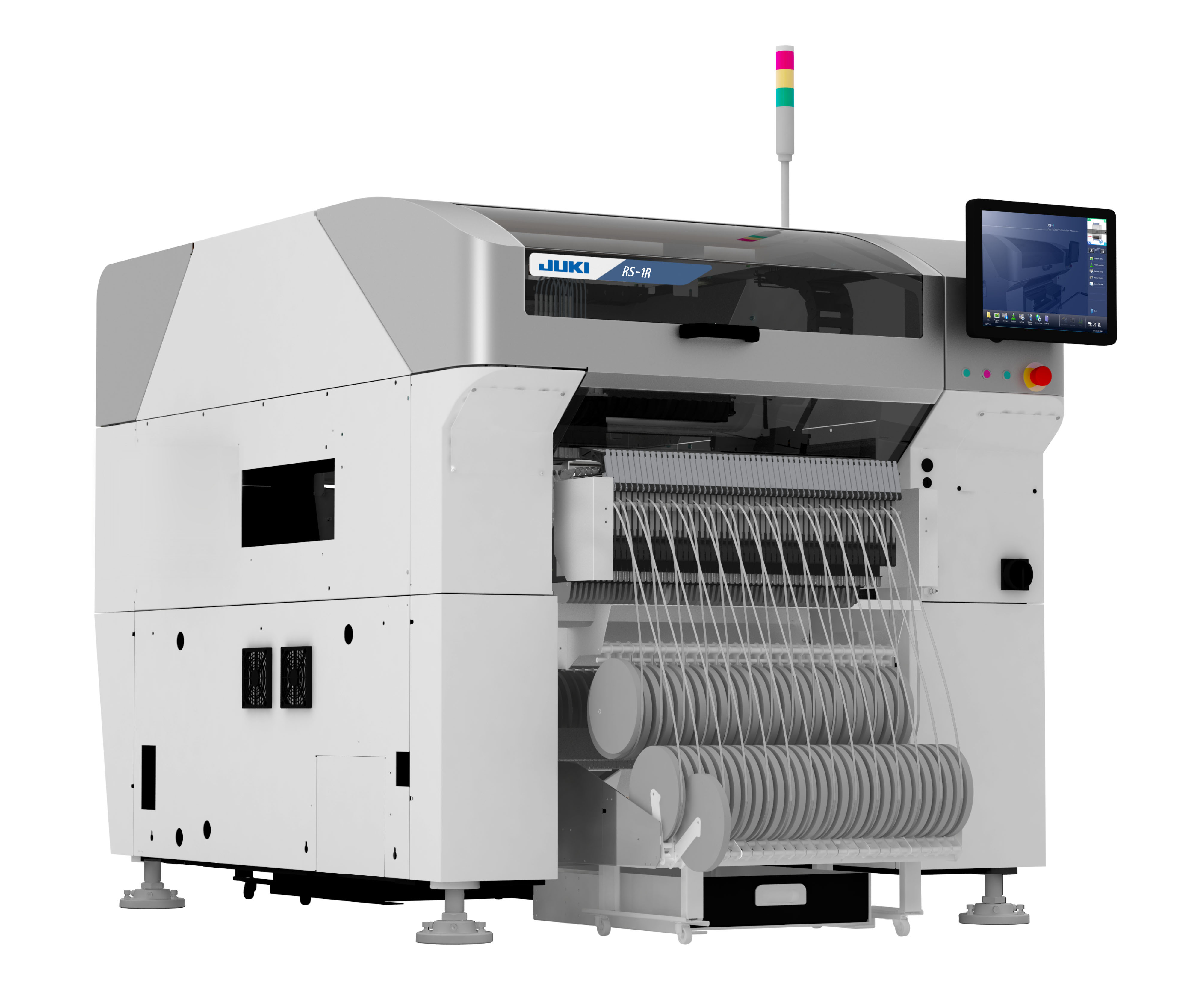
(1) Mounting speed
Speed has always been the advantage of turret-type placement machines, but with the development of technology, new placement machines are continuously introduced, and the placement speed of several new models of structural placement machines and modular placement machines has exceeded A new type of turret-type placement machine. This can be seen from the functional parameter table of different types of placement machines.
(2) Mounting accuracy
With the wide application of micro components and fine-pitch components, current electronic products have put forward higher requirements on placement machines in terms of placement accuracy. A few years ago, the acceptable accuracy standards in the industry were still 0.1mm (chip components) and 0.05mm (IC components). Now, the standard has dropped to 0.05mm (chip components) and 0.025mm (IC components) trends.
Now it is difficult to exceed the 0.05mmZ good tower mounter can only reach the accuracy level. The most advanced structural placement system can reach 4σ, 25μm accuracy. Machines that reach this talent are not very fast.
(3) The range of components that can be pasted
Affected by the feeding method, the turret mounter can only install tape packaging or bulk packaging components, even if its vision system can handle these components, pipes and trays cannot be installed. Density pitch components generally use the disc packaging method, so the turret placement machine is the weakest in this indicator. And limited by the mechanical structure, there is little room for improvement.
(4) Mounter x-y movement organization
The function of the xy motion organization is to drive the reciprocating motion of the x-axis and the y-axis of the sticking head in two directions, so that the sticking head can reach the designated position accurately and smoothly.
Now there are several different composition methods for the xy motion organization on the placement machine, namely the servo motor drive form driven by the ball screw linear guide rail; the servo motor drive form driven by the synchronous belt linear guide rail; the linear motor drive form.
These drive forms are similar in structure and all require linear guides as guides, but the transmission forms are different.
The following is the servo motor drive method, which is driven by a ball screw linear guide.
Figure 8 shows a basic placement machine xy motion organization. The x-axis servo motor uses ball screws and linear guides mounted on the beam to drive the x-axis movement of the placement head, and the y-axis servo motor uses balls mounted on the frame. The lead screw and linear guide drive the entire beam to move in the y-axis. These two motions are combined to form a planar xy motion organization that drives the high-speed motion of the head xy.
In the y-axis direction, since the beam with a certain length is driven, the two ends of the beam must be installed on a fixed linear guide, and there is a certain span between the two guides. The motor and the transmission ball screw cannot be installed in the middle of the two guides. , can only be installed close to the inside of a rail. In this way, when the component of the head and the span of the beam reach a large value, the head moves near the guide rail at one end away from the motor, and the combination of the y-axis ball screw and the beam generates an unbalanced angular sway moment, and the acceleration, deceleration and positioning functions of the y-axis will be was greatly affected. To reduce this disadvantage, many placement machines now use dual motor drives in the y-axis.
The dual-motor drive form is selected, and the two motors drive the movement of the beam harmoniously, which improves the positioning stability and reduces the positioning time, thereby improving the speed and accuracy of the y-axis at the positioning time.
In order to achieve higher placement speed on a single placement machine, the current high-speed placement machine uses double beam/double head technology,
JUKI structural development, the x-beam system moves along the y-direction, and there are two stickers on both sides of the x-beam. Each sticker can be installed separately from two sides. The pick-up stations on both sides of the x-beam pick up the components and install them. The PCB board can move in the x, y plane.
The improved version of JUKI's Figure 10 model adopts the double-improved X-beam double-head structure. The placement machine of this structure has two x beams and a double placement head system on both sides of the board feeding mechanism, and there are reclaiming stations and placement areas on both sides.
The placement machine has high requirements for speed and precision. A device cycle (that is, the placement machine completes a material patch action), including the time when the device spindle absorbs the component, the time when it moves to the static lens, the time when the static lens camera is moved, the time when it moves to the device position, the time when the component offset is corrected, When installing the spindle device components, the total time should reach 1~2s. When the number of nozzles on each placement head of the placement machine is small (less than 3), the key factor for the xy motion organization to drive the placement is the length of the movement time of the motion organization to drive the placement head. In order to meet the requirements of high-speed placement, the x and y directions should be moved at a speed of 1.25m/s or higher, and there should be a larger acceleration and deceleration (1g ~ 2g), and the acceleration and braking time should be as far as possible. Maybe short. In this way, the placement machine cannot make the moving parts very solid and heavy like the CNC machine tool. On the contrary, it should reduce the mass and inertia of high-speed moving parts as much as possible, such as cars and airplanes, in order to achieve sufficient motion positioning accuracy and the highest possible acceleration and deceleration function in both, Z, to achieve the best inertia matching.
(5) Discussion on the function of placement machines at home and abroad
Japan's Matsushita and other foreign placement machines have always been in the forefront, JUKI heavy machine, Yamaha, SONY placement machine, FUJI Fuji NXT, South Korea's Samsung placement machine, MIRAE placement machine, Germany's ASM Siemens SIPLACE American global high-speed placement machine, Holland Philips Ambion placement machine, etc. have developed a very mature product series.
Georgia Institute of Technology D. A. Bodner, M. Damrau et al. used the VirtualNC imitation tool and the electronic placement equipment Siemens80S20 as the prototype to establish the corresponding digital prototype model, as shown in Figure 12. According to the three core components of the device system, the plate structure and the feeding system, the function of the whole machine is studied in detail, and the factors affecting the device speed and how to obtain the Z device cycle time are analyzed.
According to the concept of multi-body simulation, Feldmann and Christoph of the University of Erlangen in Germany integrated multi-body dynamics simulation software, finite element analysis software and manipulation simulation tools to establish an inductive multi-body simulation analysis platform as shown in Figure 13. The SiplaceF4 placement machine is a prototype machine, and a multi-body simulation digital prototype model of the placement machine is established, and the characteristics, flexibility, oscillation characteristics and thermal deformation of the placement machine moving target are discussed. The method of establishing linear restraint on the flexible body is mainly introduced. The "TimingMechanism" in the ADAMS/ENGINE module establishes the imitation model of the motor-driven toothed belt.
Dr. Masri Ayob from the University of Nottingham, UK, studied the optimization of multi-head sequential placement machines, starting from improving step-mounting operation, enhancing motion control, nozzle selection and feeding assembly.
The placement machine was once one of the key development projects of electronic equipment in my country's "Seventh Five-Year Plan", "Eighth Five-Year Plan", "Ninth Five-Year Plan" and "Tenth Five-Year Plan". In the past 20 years, some domestic research institutes, universities and factories have carried out the development of various SMT equipment (referring to silk screen, patch, welding and other equipment) on the production line.
Since the introduction of the first color TV production line in my country in 1978, the Second Research Institute of the Ministry of Electronics has started the development of the placement machine. In the future, 56 scientific research organizations of the Ministry of Electronics, 4506 factories of the Ministry of Electronics, the Second Research Institute of the Ministry of Aerospace, Guangzhou Machine Tool Research Institute and other scientific research organizations will be developed separately, and a lot of scientific research results have been achieved. Although these research results have not been industrialized, they have accumulated valuable experience for latecomers.
The discussion on the proofreading of SMT placement machines in domestic colleges and universities has now ended. For example, Yan Hongchao and Jiang Jianguo of Xidian University used an improved hybrid genetic algorithm to optimize the placement machine assembly process; Li Lei and Du Chunhua of Liang'an Jiaotong University discussed the visual inspection algorithm of the placement machine; Yang Fan of Southwest Jiaotong University discussed SMT placement machine positioning motion control; Long Xuming summarized the visual system of the placement machine; Liu Jinbo of Shandong University discussed the motion control system of the wedge placement machine; Mo Jinqiu, Cheng Zhiguo, Pu Xiaofeng discussed the mechanical and electrical engineering of Shanghai Jiaotong University. In the control system of the placement machine, Yu Xinrui, Wang Shigang, and Liu Shaojun of the CIM Microelectronics Equipment Research Institute discussed the image processing technology of the placement machine system, and Tian Fuhou and Li Shaoyuan of the Automation Research Institute optimized the placement of the placement machine feeder distribution and its genetic algorithm ; Huazhong University of Science and Technology Wang Hongsheng and Shi Tielin discussed visual images; South China University of Technology cooperated with Fenghua High-tech to conduct related discussions on visual inspection, image processing, motion control system, and efficiency optimization.
(6) Conclusion
The placement machine can be divided into special-purpose type and general-purpose type. According to the different components and the general degree of placement, there are Chip-specific type and IC-specific type. The former mainly seeks high speed, and the latter mainly seeks high precision; general types can Chips can also be pasted with ICs, which are widely used in the production line of continuous production equipment with medium output value. The high adaptability of general-purpose placement machines is a compromise between precision and speed. Its installation speed is slower than that of high-speed installation machines, and its installation accuracy is lower than that of fine installation machines. The development of high-speed placement machines has reached a certain limit. Now, placement machine manufacturers are primarily developing general types to meet more device process requirements. Since the post-packaging and placement processes have begun to be integrated with each other, higher requirements have been placed on the precision of the placement machine.
The requirement for high speed and high precision is the primary difficulty for SMT to develop a placement machine. To deal with the contradiction between high speed and high precision, it requires the perfect combination of multiple disciplines, and the organic combination of demand planning, simulation, technology, assembly, and inspection, in order to develop a high-level placement machine. However, since the manufacture of placement machines is very dependent on the development of basic industries, it also greatly prevents the development of high-speed and high-precision placement machines.