

For DIP mounter operation method many people just contact is not too well understood, some old mounter operators on the mounter various parts at the same time is also half-knowledge, so it is easy to appear to lead to system failure, the following small to everyone to introduce the analysis of the mounter of each important component parts, so that can help more people reasonable operation of the mounter.
One, the host
1. main power switch: turn on or off the mainframe power.
2, visual display: display China moves a lens to analyze the image obtained or components and marks of the identification development.
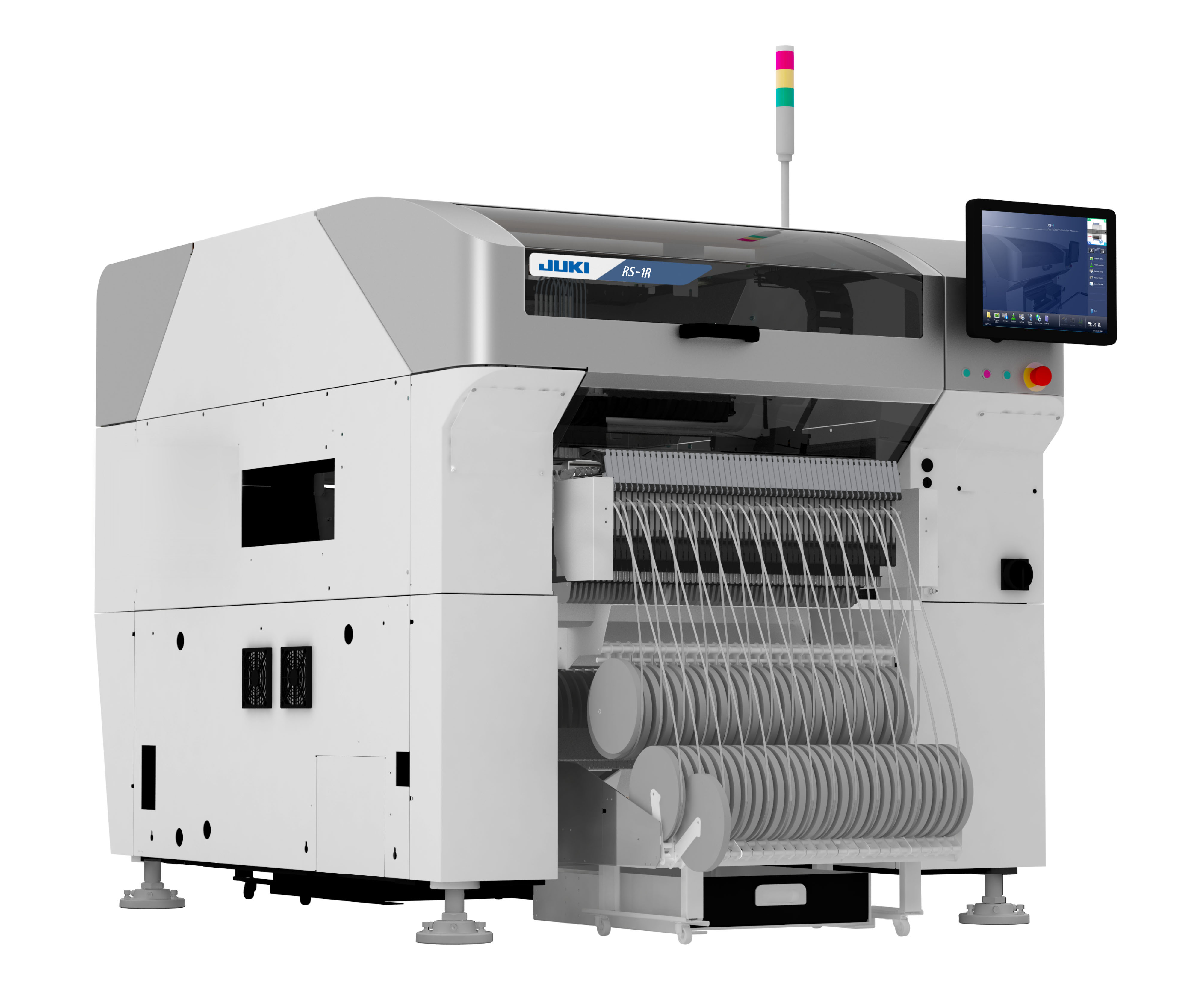
4. Warning light: indicates the technical conditions of operation when the automatic bonder is in green, yellow and red.
Green:the machine is in automatic operation
Yellow: error (return to the origin between can not be effectively executed, picking error, identification system failure, etc.) or interlocking equipment generated.
Red:Machine is in emergency stop (when the machine or ypu stop button is pressed)
Emergency stop button:Pressing this button immediately triggers an emergency stop.
II. Working head assembly
1.Working head assembly:Moves in XY direction (or X direction) to pick up parts from the feeder and mount them on the PCB.
2. Work head assembly for moving handle: when the servo system control can be lifted, you can use your hand in each development direction as well as moving, when moving the work head assembly by hand usually use this handle.
Third, the vision system
1. Moving lens: used to identify the mark on the printed circuit board or track the location or coordinates of the shot.
Independent lens: used to identify components, mainly those with pins QPF.
3.Backlight component:When it is identified by the independent vision lens, the element is illuminated from the back.
4. Laser parts:By using the laser beam can be used to carry out the identification of technical parts, mainly sheet parts.
Multi-video lens:can identify a variety of parts to speed up the identification speed.
Four, feeding platform
With loading feeder, bulk feeder and tube feeder (multi-tube feeder), which can be installed on the front or rear feeding platform of the mounter.
V. Axis structure
x:The moving head assembly is parallel to the PCB transfer direction.
Y axis: mobile management work head assembly with PCB transmission a direction for perpendicular.
Z axis: control the height of the working head assembly.
R axis: control the rotation of the nozzle axis of the working head assembly.
w-axis: adjust the width of the transport track.
Six, transport track components
1.Main stopper
2.Location pin
3.In pushing parts
4.Edge jig
5.Upward pushing plate
6.Upthrust ejector
7.Entry stopper
Nozzle station: allows the automatic exchange of nozzles. 16 nozzles can be loaded in total, 7 standard and 9 optional nozzles.
Eight. Air source components: including air filter, air pressure adjustment button and air pressure gauge.
IX. Input and operating components
1. YPU programming parts
Ready button:abnormal stop release, servo system takes effect.
2.Keypad