

The main transmission structure of the early placement machine can be classified into two types: Gantry (Gantry, also known as boom type) and turret type. The structure of the arch frame is simple, the PCB is placed on the fixed worktable, the feeder is fixed, the placement head is installed on the XY coordinate moving beam of the arch frame, and the components on the feeder are picked up by the XN movement for placement, with low cost and volume. Small, but the back and forth travel of the placement head is long, resulting in low efficiency and slow speed; the structure of the turret type is relatively complex, the PCB is placed on the XV mobile table, the feeder is placed on the single-coordinate moving guide rail, and the placement head is installed in On the convex turret, the distance from picking up the components on the feeder to placing them on the PCB is minimized, realizing high-speed placement in the true sense.
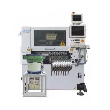
The automatic placement machine is a device used to achieve high-speed and high-precision automatic placement of components. It is the most critical and complex equipment in the entire SMT production. The placement machine is the main equipment in the SMT production line. The placement machine has developed from an early low-speed mechanical placement machine to a high-speed optical alignment placement machine, and has developed towards a multi-functional, flexible connection and modularization.
Second, the classification of placement machines
There are many manufacturers of placement machines, and there are many types. The placement machines are classified as follows.
According to the speed, it is divided into: medium-speed placement machine, high-speed placement machine, ultra-high-speed placement machine
Among them, the characteristics of the ultra-high-speed placement machine: more than 40,000 pieces/h, using a rotary multi-head system. Assembleo-FCM and FUJI-QP-132 mounters are equipped with 16 placement heads, and their placement speeds are 96,000 pieces/h and 127,000 pieces/h respectively.
Divided by function:
High-speed/ultra-high-speed placement machine, features: It is mainly based on SMD components, and there are not many varieties of SMD devices.
Multi-function placement machine, features: can mount large devices and special-shaped devices.
Divided into:
Sequential placement machine, features: it pastes the components on the PCB one by one in sequence, and this type of placement machine is usually seen.
Simultaneous placement machine, features: Using a special hopper for placing cylindrical components, all components can be placed on the corresponding pads of the PCB in one action. When the product is replaced, all the hoppers are completely replaced and are rarely used.
Simultaneous on-line placement machine, features: it is composed of multiple placement heads, and a PCB is placed in sequence at the same time. assembleon-FCM is this type.
By automation:
Automatic mechatronics placement machine, features: most placement machines are of this type.
Manual placement machine, features: The manual placement head is installed on the Y-axis head, and the X, Y, and e positioning can be corrected by the movement and rotation of the human hand. It is mainly used for new product development and has the advantage of being cheap.
3. Matters needing attention
As a high-tech product, the placement machine is very important to both machines and people to operate safely and correctly.
The most basic thing to operate the placement machine safely is that the operator should have the most accurate judgment and should follow the following basic safety rules:
1. The machine operator should be trained in the correct method.
2. Turn off the power when inspecting the machine, replacing parts or repairing and internal adjustment (the maintenance of 3 machines must be carried out when the emergency button is pressed or the power is turned off.
3. Make sure that the YPU (programming unit) is in your hand when "reading coordinates" and adjusting the machine to stop the action at any time.
4. Make sure that the "interlocking" safety equipment remains effective to stop the machine at any time. Safety checks on the machine cannot be skipped or short-circuited, otherwise personal or machine safety accidents are very likely to occur.
5. Only one operator is allowed to operate one machine during production.
6. During operation, ensure that body parts such as hands and head are out of the machine's range of motion.
7. The machine must be properly grounded (true ground, not neutral).
8. Do not use the machine in flammable gas or extremely dirty environments.
Notice:
a) Those who have not received training are strictly prohibited to operate the machine. b
) Safety is the first priority when operating the equipment. The operator of the machine should operate the machine in strict accordance with the operating specifications, otherwise it may cause damage to the machine or endanger personal safety.
c) Machine operators should be careful and careful.
Fourth, the name and function of each component of the placement machine
1. Host
1.1 Main Power Switch: Turn on or off the host power
1.2 Vision Monitor: Displays the recognition of images or components and marks obtained by moving the lens.
1.3 Operation Monitor: Display the VIOS software screen of the machine operation. If there is an error or problem during the operation, the correction information will also be displayed on this screen.
1.4 Warning Lamp: Indicates the operating conditions of the placement machine in green, yellow and red.
Green: The machine is in automatic operation
Yellow: Error (return-to-origin cannot be performed, pick-up error, recognition failure, etc.) or an interlock occurs.
Red: The machine is in emergency stop state (the machine or YPU stop button is pressed).
1.5 Emergency Stop Button: Press this button to immediately trigger an emergency stop.
2. Head Assembly
Work Head Assembly: Move in XY direction (or X direction), pick parts from feeder and place on PCB.
Head Assembly Movement Handle: When the servo control is released, you can move in every direction with your hands. This handle is usually used when moving the head assembly by hand.
3. Vision System
Moving Camera: Used to identify marks on the PCB or to track positions or coordinates.
Single-Vision Camera: Used to identify components, mainly those QPFs with pins.
Backlight Unit: Illuminates the element from the back when identified with a separate vision lens.
Laser Unit: The laser beam can be used to identify parts, mainly sheet parts.
Multi-Vision Camera: It can identify multiple parts at one time, speeding up the identification speed.
4. FeederPlate:
Tape feeders, bulk feeders, and tube feeders (multi-tube feeders) can be installed on the front or rear feeding platform of the placement machine.
5. Axis Configuration
X-axis: The moving head assembly is parallel to the PCB transfer direction.
Y axis: The moving head assembly is perpendicular to the PCB transfer direction.
Z-axis: Controls the height of the head assembly.
R axis: Control the rotation of the nozzle axis of the work head assembly.
W axis: Adjust the width of the transport rail.
6. Conveyor Unit
1. Main Stopper
2. Locate Pins
3. Push-in Unit
4. Edge Clamp
5. Push-up Plate
6. Push-up Pins
7. Entrance Stopper
8. Nozzle Station: Allows automatic exchange of nozzles, can load a total of 16 nozzles, 7 standard and 9 optional nozzles.
9. Air Supply Unit
Including air filter, air pressure adjustment button, air pressure gauge.